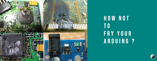
Ways to Destroy your Arduino Board
We’re going to discuss today about how you can electrically destroy your Arduino, though many of you seem to already know how to do that through unfortunate experience. You know what we mean….that funny smell, the scorch mark on a component, or the dreaded “programmer not in sync” error message — all signs that you’ve just learned a lesson the hard way.
How not to fry your Arduino?
Why are we doing this? The answer is simple If you own an Arduino, it’s good to know what is and what isn’t OK to do with it. Before you getting started with your new Arduino, it may be good to know what can damage the board.
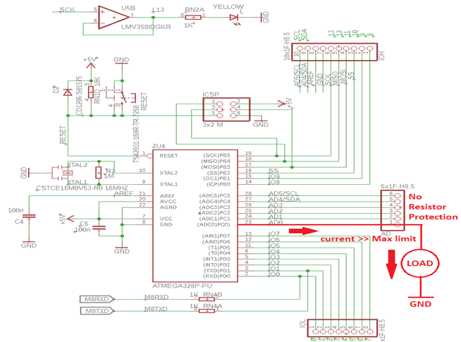
1. Drawing more than 40mA from an output pin of Arduino.
- An Arduino can only supply 40mA per output pin, so you cannot drive a motor or a speaker directly, for example, and you cannot connect an LED directly (without a resistor). Shorting an output in to the +5v, +3.3v or the ground pins, will also kill your board.
- If an output pin is at 5v for example, and you connect it to the ground, it draws large amount of current from board because there is nothing to stop, and kills your Arduino almost instantly.
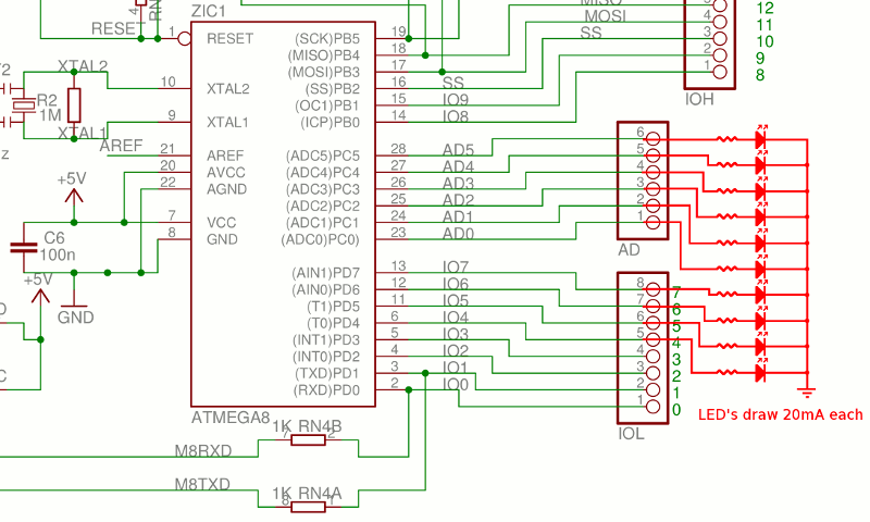
2. Drawing more than 200mA from all output pins together.
- The ATmega chip on your Arduino can only supply 200mA in total, so driving more than 10 LEDs @ 20mA each, for example, will eventually damage your board.
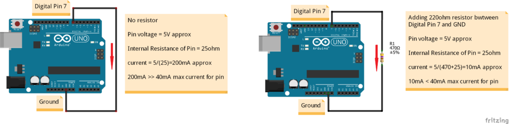
- The microcontroller datasheet specifies an absolute maximum per-pin current of 40mA. With a typical internal resistance of only 25 ohms per pin, a dead short to ground can allow as much as 200mA of current to flow, more than enough to destroy the microcontroller pin.
- The pins go through the circuit board (at bottom of PCB), so make sure you don’t place the Arduino on a conductive (metal) surface, because it will short out the pins.
- Short Circuiting, I/O Pin to ground directly will cause overcurrent flow from Pin to ground and may instantly damages the microcontroller.

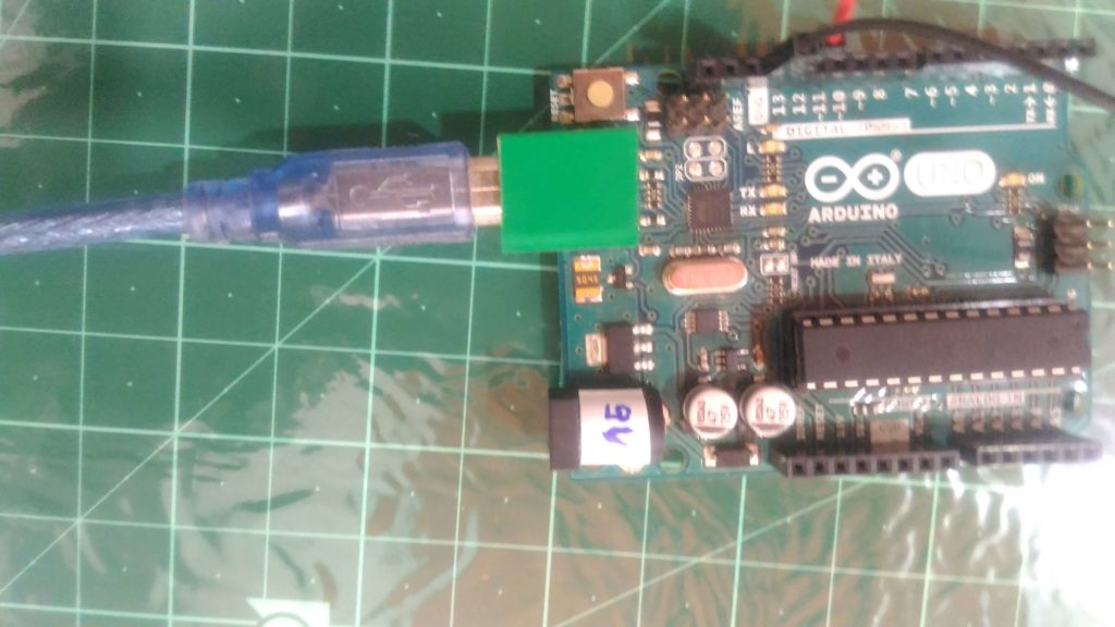
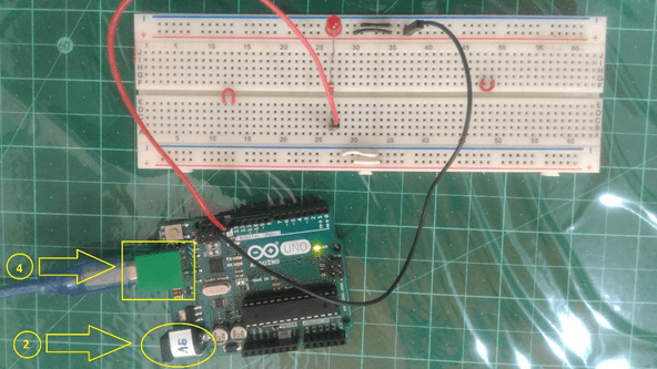
Note: You should also put something insulating like electrical tape on MiniUSB JACK of Arduino. Because sometimes it could cause short out of pins when any add-on shield pressed onto it. As shown in image below.
3. Short circuiting/ Connecting Input/output pins to each other
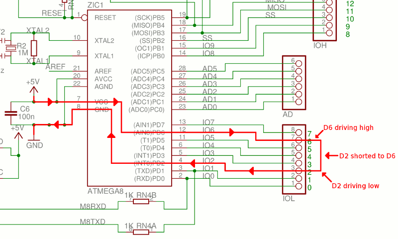
If we configured any two I/O pins to be outputs then set one high and the other one low. And If accidentally or intentionally connected them together. You have now created an over-current condition on both I/O pins and they will be damaged permanently.
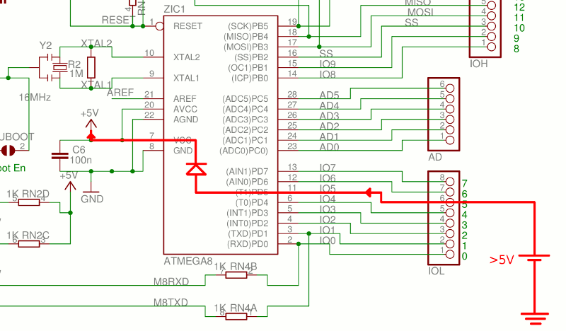
4. Supplying more than 5v (3.3v) to an input pin.
- Supplying more than the operating voltage of the Arduino on any pin is very dangerous. Some Arduinos that run at 3.3v have 5v tolerant pins, but that’s about it. This also holds true for other devices, like sensors or wireless chips: always check the voltages: if you connect the output of a 5V Arduino to a 3.3V chip, you might kill it. Following diagram shows the flow of current when overvoltage is applied to an I/O pin.
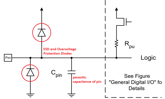
- When we apply voltage more than limit to I/O pin it forward-biases the ESD protection diode built-in to the microcontroller. Above figure show Typical ESD protection circuit, as found in an Atmel microcontroller ATmega328P datasheet.
- Once the voltage at the I/O pin is greater than the supply voltage (5V) by about 0.5V, the top diode gets forward biased and starts to conduct current. This is OK for diverting a short-duration pulse of overvoltage event, like ESD (electro-static discharge), but that diode is not meant to be on all the time. It will get simply burn out and stop protecting the pin.
- Now suppose if internal protection diode fails open, then the overvoltage will damage the I/O pin. Further if the protection diode fails by shorting out, it’s even get worse because now whatever the higher voltage is applied to the entire +5V power section on the Arduino. This means it will reach other components, like the USB interface chip, and may damage them also.
5. Supplying more than 5v to the 5v pin.
- The 5v of the Arduino board goes directly to the ATmega chip, that is rated for an absolute maximum of 6v also this voltage can also appear on your computer’s USB port, possibly damaging it if it is not smart one.
- It is a common misconception that the Arduino 5V regulator will ensure that the 5V voltage remains at 5V, no matter what. IT WILL NOT! The only thing the 5V regulator can do is control current coming from the USB port or the external DC power jack. If the current is coming from an external power source directly connected to the 5V connector pin, the regulator can do nothing about it.
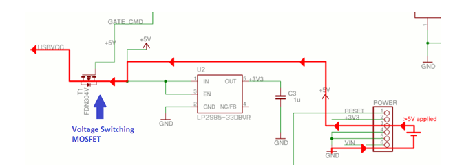
- Above image shows effect of applying more than 5V to the 5V connector pin is possible damage to the computers USB port. If the Arduino is powered from USB, then this over-voltage can cause current to flow backwards through the voltage-switching MOSFET T1 and back to the computers USB port.
6. Supplying more than 12v to the Vin pin
There’s an onboard 5v voltage regulator on the board, that will overheat and die if you feed it with more than 12v.
7. Applying reverse power polarity on Vin Pin
- If we provide power to Arduino through the Vin connector pin, but reverse the polarity (unknowingly/intentionally) of the Vin/GND power connection. Then it will destroy several devices on the Arduino.
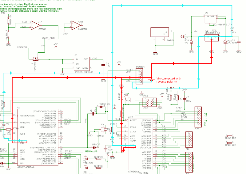
- Since there is no reverse-voltage protection on voltages applied to the Vin connector pin as shown in above diagram. Current will flow from the GND pin of the ATmega328P back up through the 5V pin, back through the 5V regulator and to Vin. The same thing will happen with the ATmega16U2 microcontroller. Both microcontrollers and the 5V regulator will get damage.
8. Applying more than 3.3V to 3.3V Pin on power header
- If we apply voltage of 3.6V or higher to the 3.3V connector pin and If Any 3.3V shields plugged in, or other devices powered from this pin, will be get damaged. If at least 9V is applied, this voltage can kill the Arduino 3.3V regulator and also feed current back into the PC’s USB port.
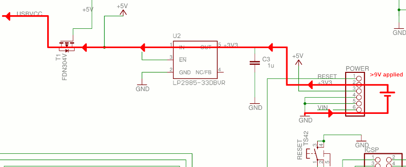
- The 3.3V connector pin has no protection circuitry. This voltage is directly connected to the Arduino 3.3V regulator and any other shields or devices that are powered by this connector pin. If the voltage exceeds 9V, the 3.3V regulator will be destroyed and may allow current to flow backwards to the 5V node, and then backwards further to the PC’s USB port. The excessive voltage will also destroy the two devices connected to the 5V node: the ATmega328P and ATmega16U2 microcontrollers.
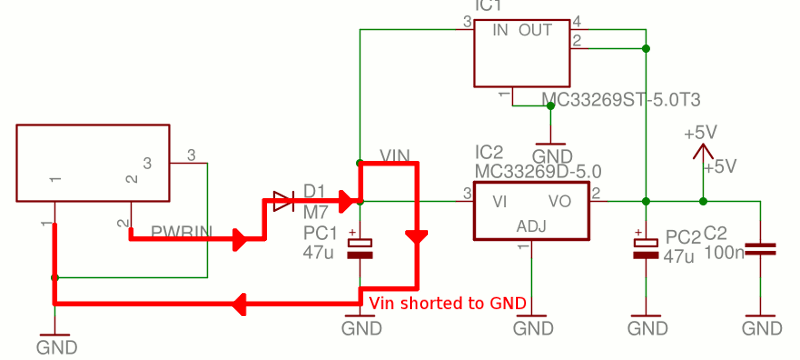
9. Short Vin to GND while Arduino is powered from the DC power.
If you short Vin to GND while Arduino is powered from the DC power. The Arduino blocking diode will be destroyed and traces on the boards PCB may melt and damaged.
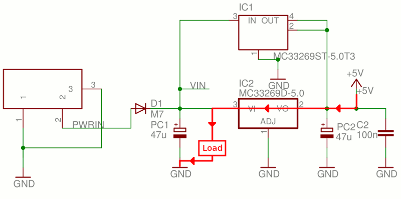
10. Apply 5V External Power with Vin Load
If we power the board from 5V applied to the 5V connector pin and you have circuitry connected to the Vin pin (or shorted Vin to GND) then current will flow backwards through the 5V regulator and destroy it.
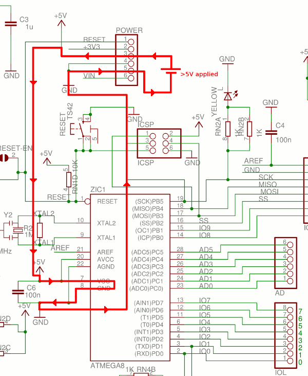
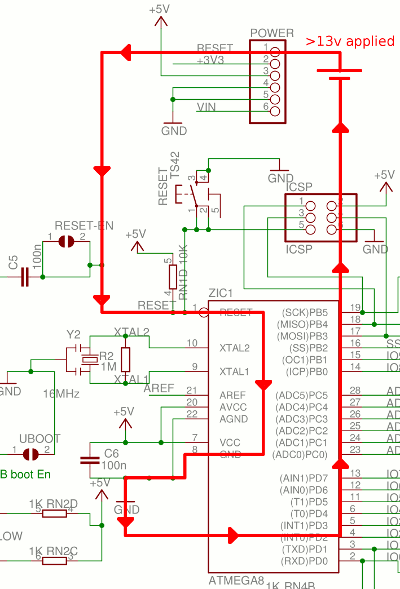
11. If we apply >13V to the Reset connector pin
If we apply >13V to the Reset connector pin. The ATmega328P microcontroller will be damaged. The Reset connector pin is directly connected to the reset pin on the ATmega328P. While this pin tolerates 13V, higher voltages will damage the device.

12. Drawing more than 500mA from the 5v pin (when running off an external power supply).
The onboard 5v voltage regulator can only supply 500mA of current. The 5v USB has a polyfuse (PTC protection fuse) to limit the current to 500mA.
13. Drawing more than 50mA from the 3.3v pin.
The onboard 3.3v voltage regulator can only supply 50mA of current. This means that you cannot connect power hungry 3.3v devices like an ESP8266 or nRF24L01 directly to the Arduino: you need an external 3.3v voltage regulator.
14. Reversing the polarity of the power supply.
If you swap the 5v or Vin pin with the GND pin, you’ll kill the board almost instantly. The barrel jack has a diode to protect against reverse polarity.
15. Connecting a load to the Vin pin while using USB power.
If you connect a load to the Vin pin while the 5v to the Arduino comes from the USB connection, current will flow backwards through the voltage regulator, damaging it.
16. Static electricity charges.
Although most of chips have clamping diodes as protection against ESDs (electrostatic discharges), it may be wise to us an anti-static wrist strap, or to remove the carpet under your desk.
Go through these links ( link1, Link2 )which provides very good explanation about arduino power management.
Best Practices :
- Use Rated power supply to the board = 9V-12V DC, 250mA-1A, 2.1mm plug size
- Put (9V) sticker/label on input DC barrel jack and also on output plug (2.1mm) of power adapter.
I fried 2 usb hubs by connecting wrong power supply to them, so be careful about powering any device. First confirm its operating voltage range, then connect appropriate power supply.
- Before interfacing board to any module, device, sensor, actuator check for logic level specifications (TTL, CMOS, RS232 etc.)
- Put proper insulation (tape) on top side of USB input connector as shown in figure, this avoids short circuiting of some shields pins. This is for protection of ‘shields pcb’ from getting short circuited when you place shield on the top of Arduino.
Summary
Before tinkering and exploring any kind of technology/device, you should first learn about its specification. It is very important to know how it works, its do’s and don’ts.
Make a habit of understanding the purpose of each and every component in the design of any technological field.
Arduino is low cost device, very simple and useful to getting started in embedded field. But one should know what not to do before getting started to dive into arduino-world. In this post I tried to focus on mistakes that I did and learned from them during my experiments with arduino.
These are my findings; you can explore more. Try to learn by making or braking things!!!!
References
In this post, most of text, images and information are taken from following websites, articles, books, ebooks, blogs, magazines. I’m so grateful to all for their valuable & informative work.
- A very good and comprehensive instructable by tttapa
- Arduino’s official website.
- rugged-circuits.com
- open-electronics.org
- sparkfun.com
- Desk of ladyada learn.adafruit.com
- Wikipedia, the free encyclopedia


