“LED blinking program in embedded systems is analogous to ‘Hello World’ program in classic programming languages”
The first program every programmer learns consists in writing enough code to make their code show the sentence “Hello World!” on a screen. The blinking LED is the “Hello World!” of physical computing. In this post we’ll see how to Blink an LED using Arduino Uno board.
Blinking an LED
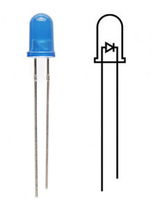
LEDs (that’s “ell-ee-dees”) are a particular type of diode that convert electrical energy into light. LED – Stands for Light Emitting Diode. You can find them in almost all electronic devices. They comes in different colors, shapes and sizes. LEDs are small, powerful lights that are used in many different applications. To start off, we will work on blinking an LED, the Hello World of microcontrollers.
That’s right – it’s as simple as turning a light on and off. Blinking means making this LED turn on for some time and then turn it off. This phenomenon can be controlled by Arduino which we are going to program for.
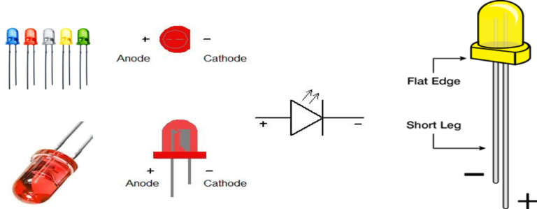
Above figure shows how an LED looks like? Its Symbol. LEDs have polarity, which means they will only light up if you orient the legs properly. Like diode LED also has two terminals, cathode and anode. Cathode can be identified as shorter than anode if we hold LED. Some types of LED’s also have flat edge on side of cathode as shown in figure.
Suggested readings – To learn more about LED’s check out these links :
Circuit Diagram –
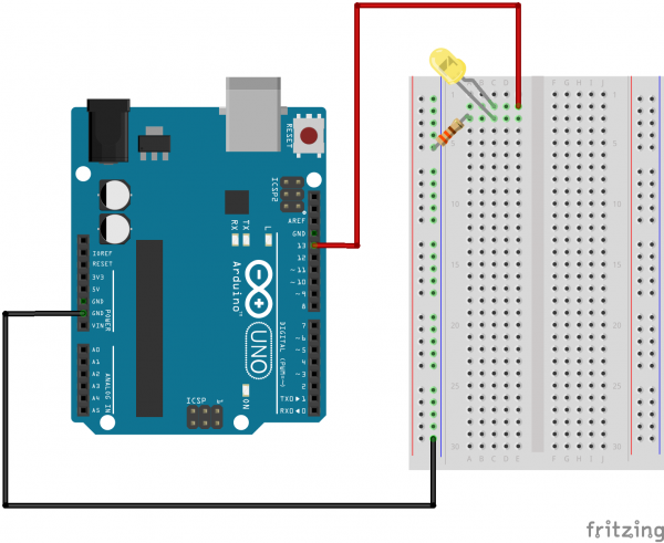
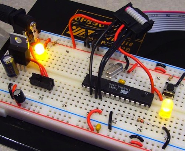
Hardware Hookup :
- Here in schematics RED wire is used to connect to positive terminal of LED. Black wire is connected to GROUND pin through 330 Ohm Resistor (Color code – Orange, Orange, Brown).
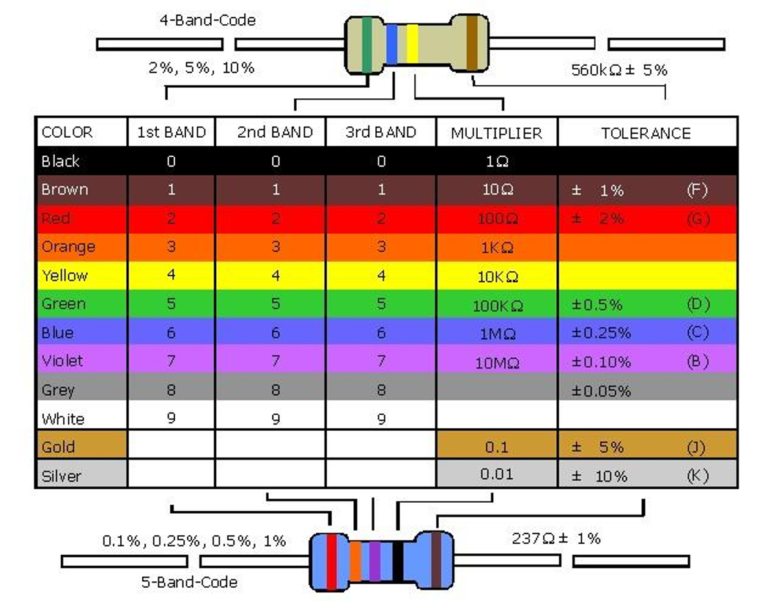
- Resistors are the most ubiquitous of electronic components. They are a critical piece in just about every circuit. Resistors are electronic components which have a specific, never-changing electrical resistance. The resistor’s resistance limits the flow of electrons through a circuit.
Following figure shows how to find resistor value using color codes
Suggested readings – To learn more about Resistors check out these links :
- Resistor Basics
- Resistor Application
- Pay special attention to the component’s markings indicating how to place it on the breadboard.
Polarized components can only be connected to a circuit in one direction. e.g – LED used here has polarity as mentioned above. The negative side of the LED is the short leg, marked with a flat edge.
- Breadboard – Breadboards are one of the most fundamental pieces when learning how to build circuits. A breadboard is a construction base for prototyping of electronics. In short these are platforms which allows you to easily connect components together.
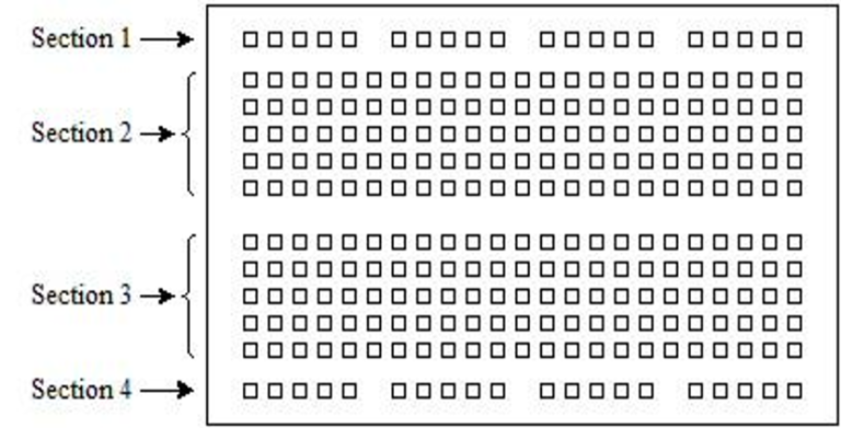
Horizontal holes in Section 1 are connected together (Short Circuited) . Usually used for +5V
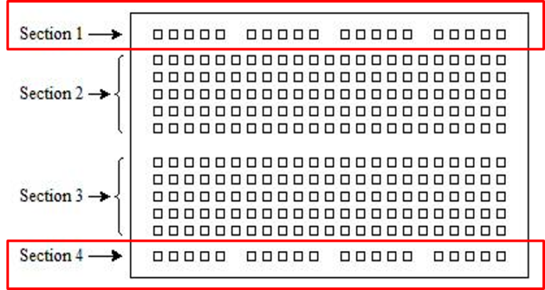
Horizontal holes in Section 4 are connected together. Usually used for GND
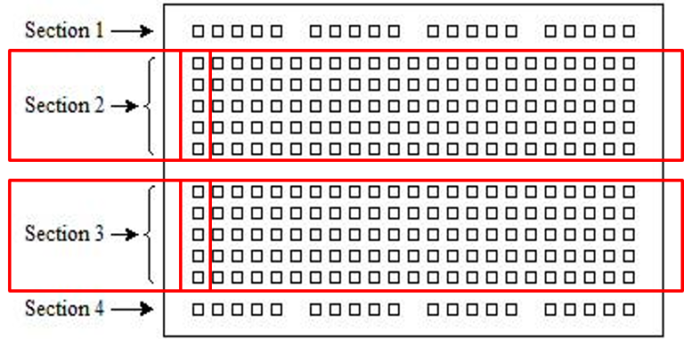
Vertical holes in Section 2 are connected together, (Short Circuited vertically).
Vertical holes in Section 3 are connected together, (Short Circuited vertically).
Suggested readings – To learn more about Breadboard check out these links :
Why there is need of Resistor in this Circuit ?
We must consider two things here –
1. Current Sourcing capacity of Arduino Pin.
2. Maximum current rating for LED.
1. As per Arduino/MCU-ATmega datasheet approx 40mA maximum current can be passed through any pin of arduino without destroying it, if current goes beyond 35-40mA microcontroller port pin get damaged and subsequently MCU itself.
2. Most of the LED are rated for maximum current passes through them. Generally LED can withstand upto 20mA current, if current goes beyond 20mA LED burns/melts.
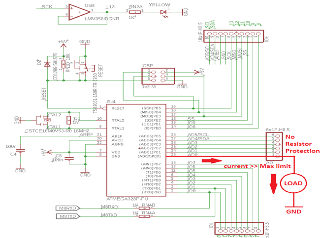
Since Arduino’s Pin/ i.e ATmega8/32 Pin has internal resistance typically 25 Ohm if we do not connect any resistance across it then Current passing through It will be = I = 5V/25ohm = 200 mA !!! it will definitely bring smoke out of both LED and Arduino.
So to avoid such damages,
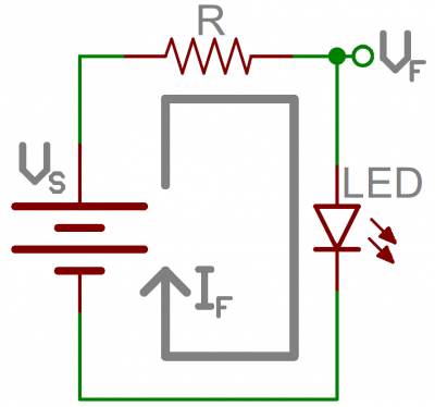
Here Vs = source voltage = Arduino Pin Voltage = 5V;
Vf = LED forward Voltage drop = 1.8~2V
So suppose for 10mA LED current which is < 40mA (Max rated Pin current) also <20mA (max rated LED current) :
V=I/R therefore R= (Vs-Vf)/10mA = 277 Ohm approx
Power Dissipation = W=(Vs-Vf)*I = 0.0320 W
So desirable resistance should be 330 Ohm & of 1/8 watt.
As shown in schematic, there is a 330 Ohm resistor connected between ground and negative terminal of LED. This resistor is used to limit the current flow through Pin as well as through LED called as current limiting resistor.
Suggested readings – To learn more about current Limiting Resistors check out these links :
Software Procedure and Coding
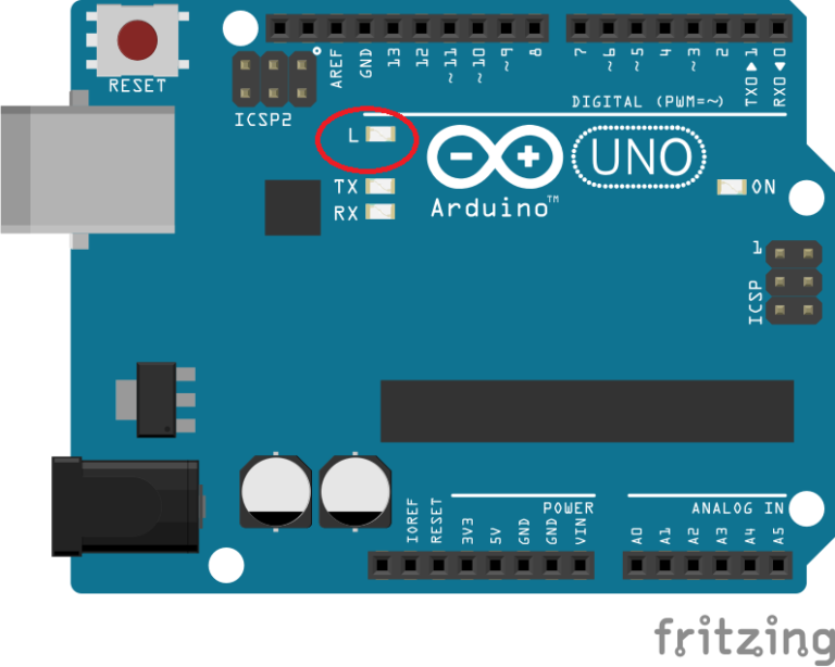
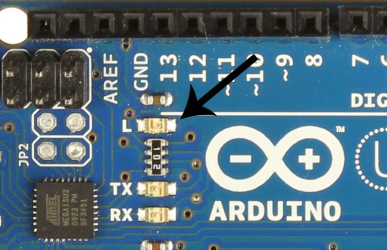
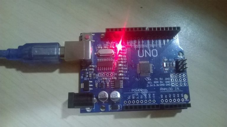
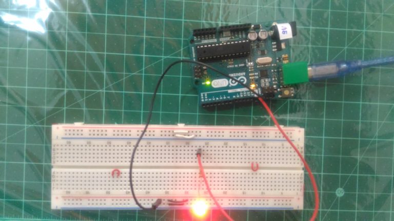
- We will perform two experiments here, first we’ll blink the onboard LED of Arduino Uno Development Board also called as Built-In LED and then we’ll blink the externally connected LED.
- As shown in figure below Built in LED of Arduino Uno board is located besides Arduino logo and is ‘marked as L’
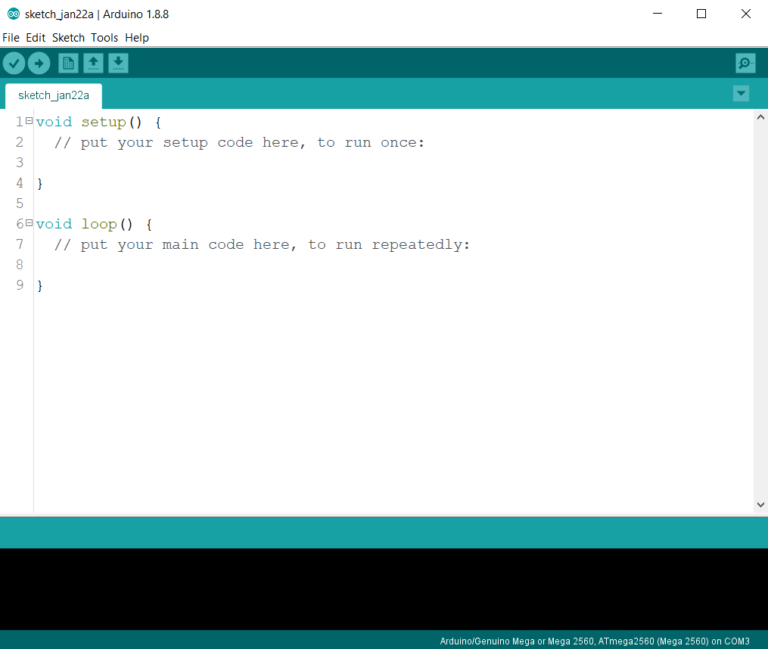
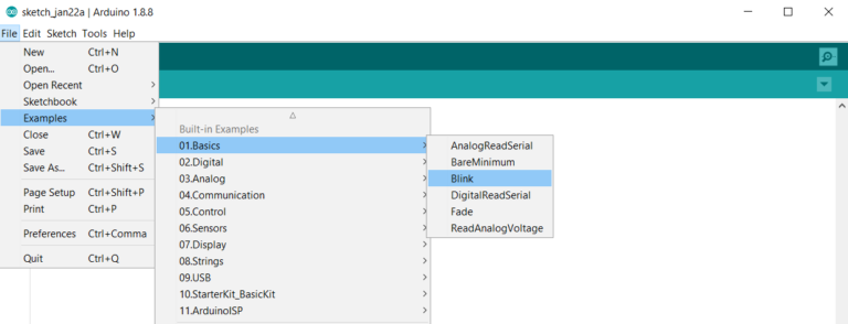
- After you build the circuit plug your Arduino board into your computer, start the Arduino Software (IDE) and enter the code below. You may also load it from the menu File/Examples/01.Basics/Blink.
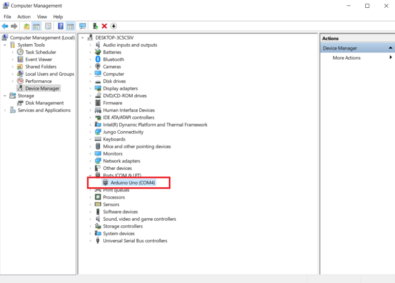
- Then connect your Arduino board to your computer using USB cable. If you connecting it first time then wait for drivers to install automatically. Check ‘Device Manager’ (in case of windows), To verify all drivers are loaded/installed successfully. If your device/board is not listed under ‘COM’ ports in device manager as shown in figure below, the you have to install the Arduino USB drivers manually.
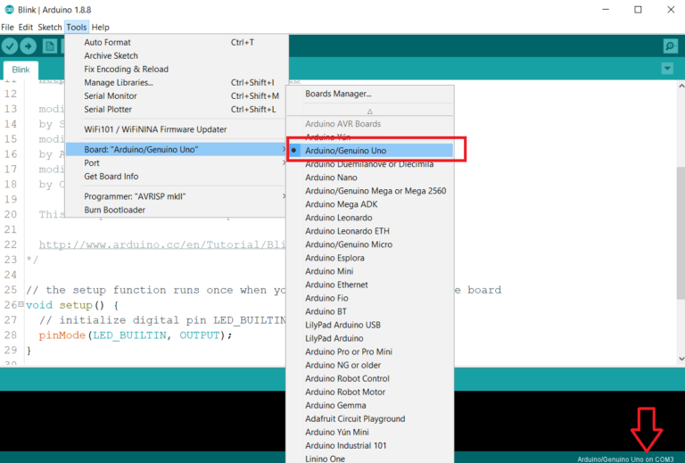
- Once your Arduino board is listed in COM ports note the com port number from device manager and open Arduino IDE. Goto Tools->Board->Arduino/Genuino Uno. Select your board e.g Arduino/Genuino Uno.
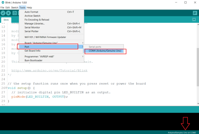
- Then Select com port as Tools->Port->COM4* likewise
(*In my case com port number was COM4 in your case it may be different) - After selecting board name and com port will appear in lower right corner of IDE window, as shown in following figure.
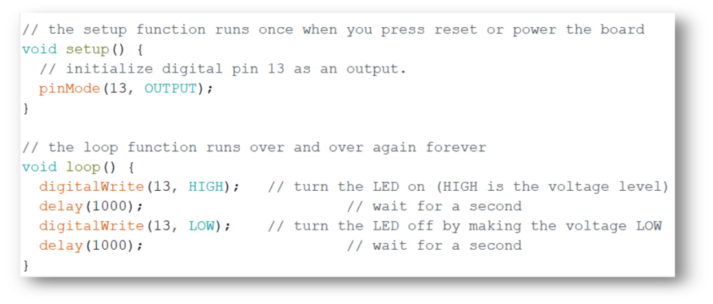
Code
Most Arduino boards contain a light-emitting diode (LED) and a load resistor connected between pin 13 and ground, which is a convenient feature for many tests and program functions. A typical program for a beginning Arduino programmer blinks a LED repeatedly.
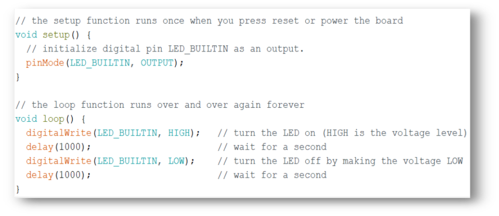
- void setup() {} – This function is called once when a sketch starts after power-up or reset. It is used to initialize variables, input and output pin modes, and other libraries needed in the sketch.
- void loop() {} – After setup() function exits (ends), the loop() function is executed repeatedly in the main program. It controls the board until the board is powered off or is reset.
- pinMode(LED_BUILTIN, OUTPUT) − Before you can use one of Arduino’s pins, you need to tell Arduino Uno R3 whether it is an INPUT or OUTPUT. We use a built-in “function” called pinMode() to do this.
- digitalWrite(LED_BUILTIN, HIGH) − When you are using a pin as an OUTPUT, you can command it to be HIGH (output 5 volts), or LOW (output 0 volts). Which subsequently makes LED as “On” and “Off” respectively.
- delay(1000) – this is just delay function used to include 1000 mSec == 1sec delay in LED on and OFF period.
- // or /*——*/ – used to make useful comment about code to understanding purpose, anything come in this section i.e after // or between /*–*/ will not compiled by IDE
Please note that same code can be used to blink external LED which is connected to pin 13 of Arduino because built in LED is also connected to same pin.
Compile/Verify
To compile/verify the code for the Arduino board follow the procedure given below,
- Make sure that board is connected and com port is selected in IDE, after that go to
Sketch->compile/verify or Press (ctrl+R) keys to complile the code. Or you can also click tick sign (✓) on menu of arduino IDE.
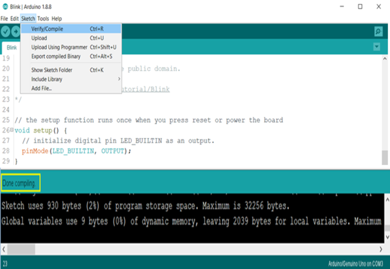
- If you see ‘Done compiling’ as shown in above figure means your program have been successfully compiled and you are ready to upload it on your board.
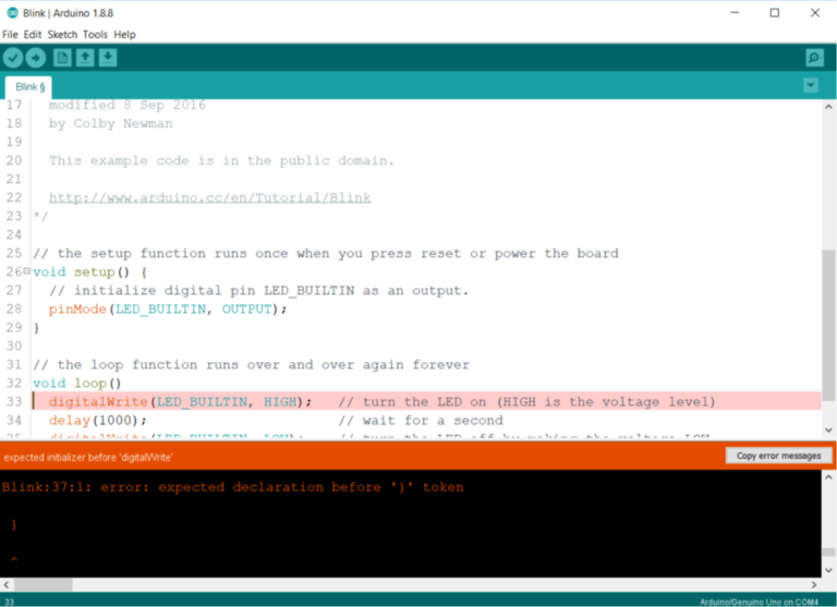
- If there are errors in the program then they will notified in this section as shown below.
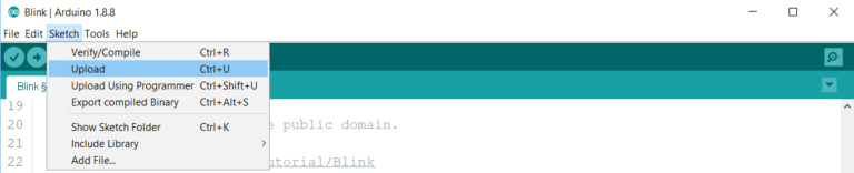
Upload
To upload the code the Arduino board follow the procedure given below,
- Make sure that board is connected and com port is selected in IDE, after that go to
Sketch->Upload or Press (ctrl+U) keys to upload the code. Or you can also click right arrow sign (→) on menu of Arduino IDE.
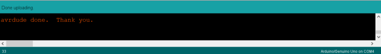
- If all goes well (means if there are no errors) then you will see following window after successful upload
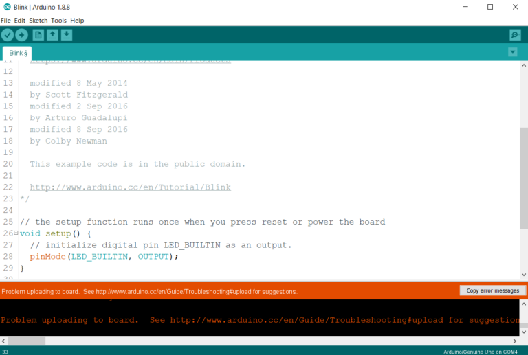
- If any error occurs during uploading you will window somewhat like figure shown below, then troubleshoot your connection, recheck port and correct board selection.
Results
following figures shows the outputs of these experiments, i.e both built-in and external led blinking
Summary
This post is just about how to get started with Arduino board – by just overview of how to program Arduino for blinking an LED. There are tons of tutorials and guides on internet about LED blinking and other basic interfacings of Arduino.
References
In this post, some text, images and information is taken from
- Wikipedia, the free encyclopedia
- Arduino’s official website.
- Sparkfun.com
- Fritzing.com


